Table of Contents
Overview
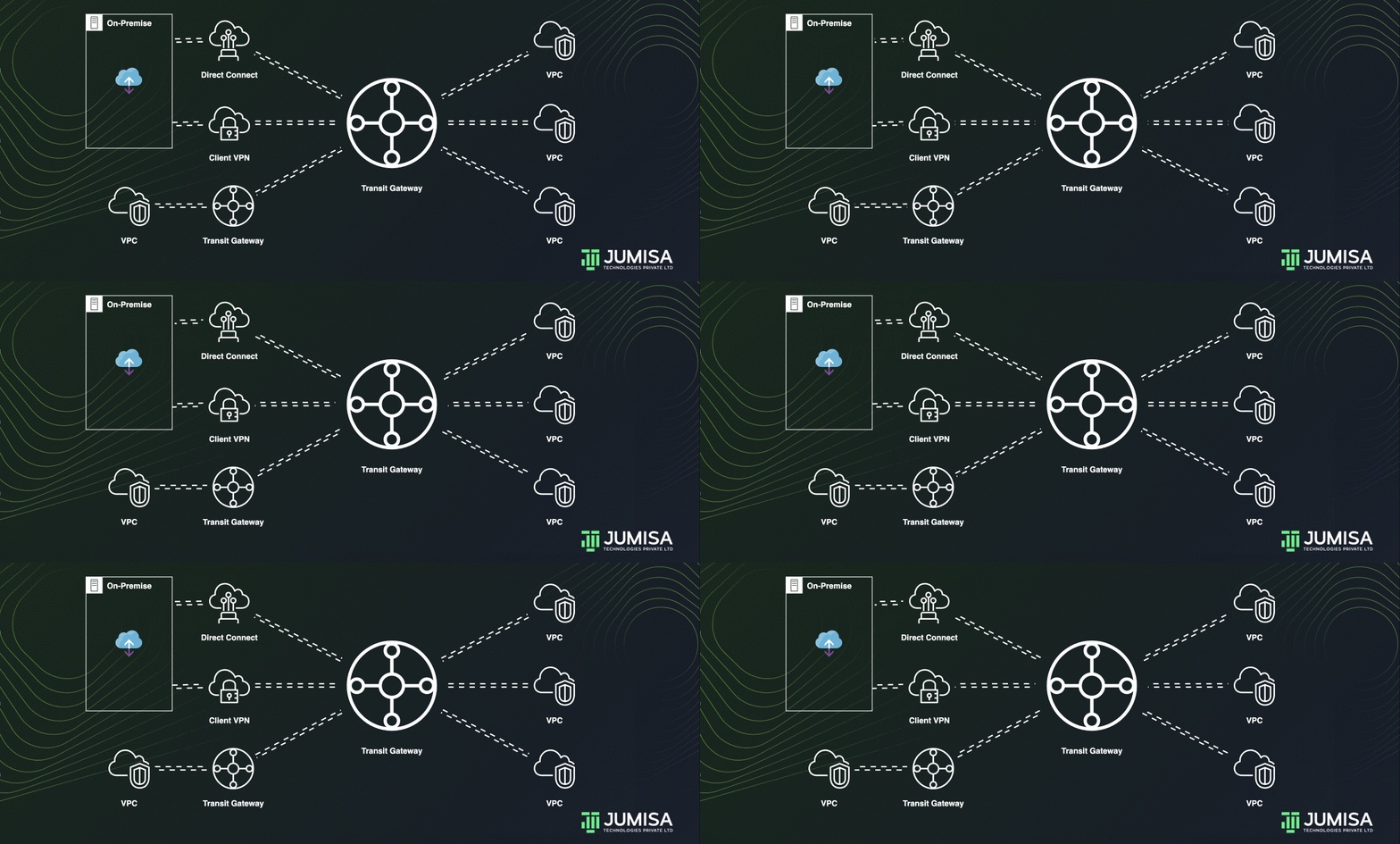
AWS Transit Gateway acting as a cloud router and helps to design and implement networks at scale. As the network grows, the complexity of managing incremental connections can slow you down.
Transit Gateway connects the VPCs and on-premises networks through a central hub.
Inter-Region peering connects transit gateways together using the AWS Global Infrastructure.
All network traffic between AWS data centres is automatically encrypted at the physical layer.
This connection simplifies your network and puts an end to complex peering relationships.
Advantages of Transit Gateway over VPC peering
- Deliver applications around the world: Build, deploy, and manage applications across thousands of VPCs without having to manage peering connections or update routing tables.
- Rapidly move to global scale: Share VPCs, Domain Name System (DNS), Microsoft Active Directory, and IPS/IDS across Regions with inter-region peering.
- Smoothly respond to spikes in demand: Quickly add Amazon VPCs, AWS accounts, virtual private networking (VPN) capacity, or AWS Direct Connect gateways to meet unexpected demand.
- Host multicast applications on AWS: Host multicast applications that scale based on demand, without the need to buy and maintain custom hardware.
Transit Gateway Route table
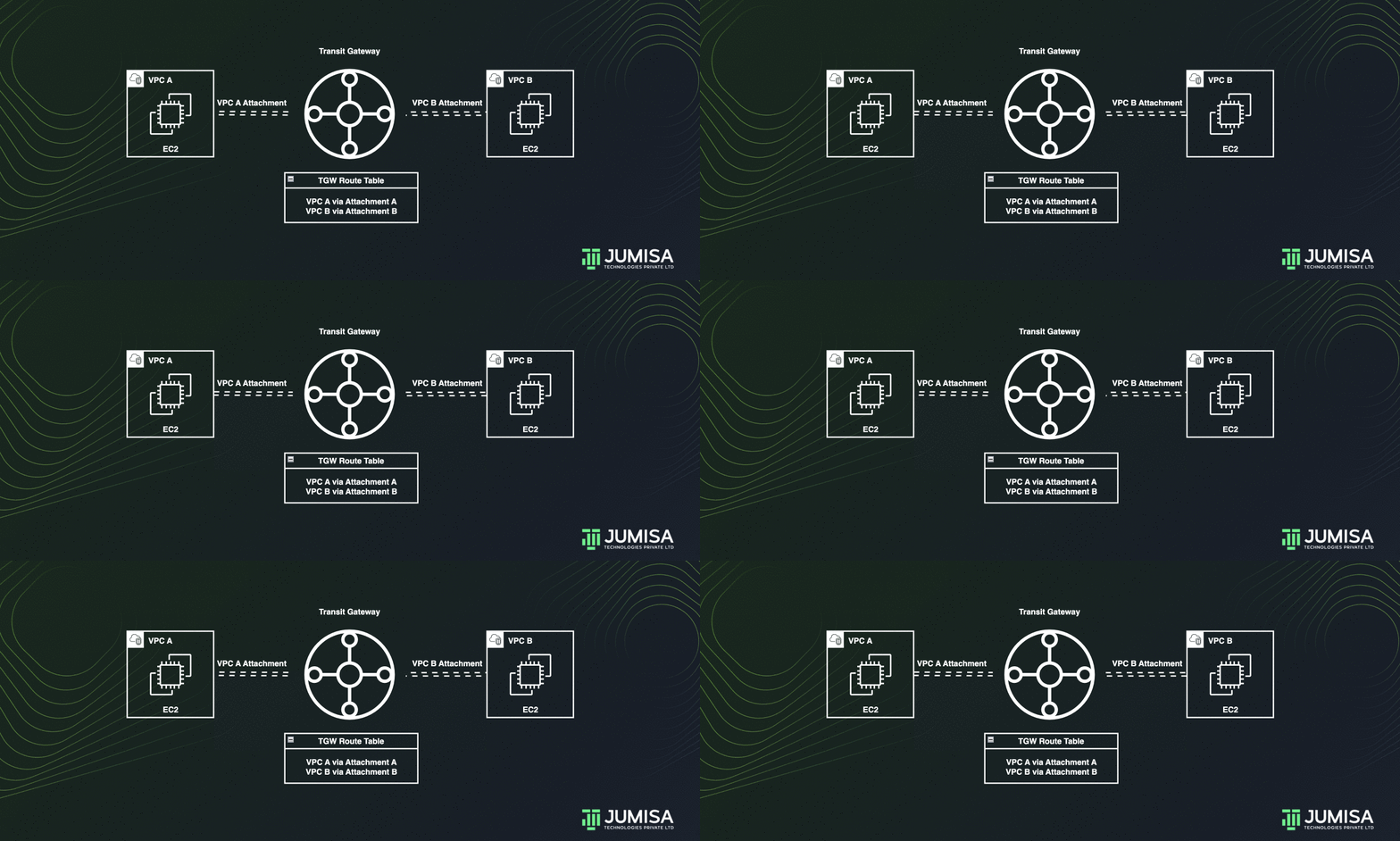
The following is an example of a default transit gateway route table.
The CIDR blocks for each VPC propagate to the route table. Hence, each attachments can route packets to the each other.
| Destination | Target | Route type |
|---|---|---|
| VPC A CIDR | Attachment for VPC A | propagated |
| VPC B CIDR | Attachment for VPC B | propagated |
| VPC C CIDR | Attachment for VPC C | propagated |
Transit gateway routes IPv4 and IPv6 packets between attachments using transit gateway route tables.
These route tables can be configured to propagate routes from the route tables for the attached VPCs, VPN connections, or Direct Connect gateways. Static routes can also be used.
When a packet comes from one attachment, it is routed to another attachment using the route that matches the destination IP address.
Availability Zone selection
When a VPC is attached to a transit gateway, one or more Availability Zones must be enabled to be used by the transit gateway to route traffic to resources in the VPC subnets.
To enable each Availability Zone, exactly one subnet must be specified. The transit gateway places a network interface in that subnet using one IP address from the subnet.
After you enable an Availability Zone, traffic can be routed to all subnets in the VPC, not just the specified subnet or Availability Zone.
However, only resources that reside in Availability Zones where there is a transit gateway attachment can reach the transit gateway.
Transit Gateway Use cases
Listed below are a few common use cases for transit gateway. But it is not limited to these. There are lot of possibilities how a transit gateway can be used.
- Centralized router
- Isolated VPCs
- Isolated VPCs with shared services
- Peered Transit Gateway
- Centralized outbound routing
- Appliance VPC
Centralized router
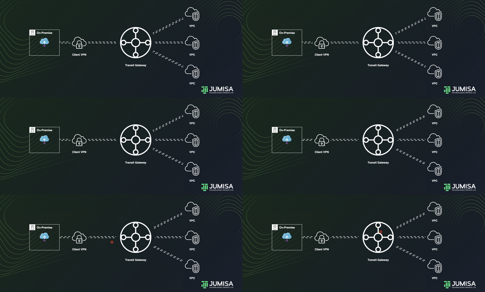
Let us assume three VPC attachments and one Site-to-Site VPN attachment to the transit gateway.
Packets from the subnets in VPC A, VPC B, and VPC C that are destined for a subnet in another VPC or the VPN connection first route through the transit gateway.
VPC route tables
The route tables of the VPC must have the route entries as follows.
- The first entry is the default entry on the VPC route table for local IPv4 routing in the VPC that enables the instances in this VPC to communicate with each other.
- Then the entries that route all other VPCs traffic to the transit gateway.
The below table shows the Route table entries for VPC A where traffic from VPC B, VPC C, and the VPN through the transit gateway is allowed.
| Destinaltion | Target |
|---|---|
| VPC A CIDR | Local |
| VPC B CIDR | TGW |
| VPC C CIDR | TGW |
| VPN CIDR | TGW |
Transit gateway route table
The below table shows the Route table entries for the TGW route table.
| Destination | Target | Route type |
|---|---|---|
| VPC A CIDR | Attachment for VPC A | propagated |
| VPC B CIDR | Attachment for VPC B | propagated |
| VPC C CIDR | Attachment for VPC C | propagated |
| VPN CIDR | Attachment for VPN connection | propagated |
Similarly on the customer gateway Border Gateway Protocol table the CIDRs of all the VPCs are whitelisted.
Isolated VPCs
Transit gateway can be used as multiple isolated routers. This is like using multiple transit gateways but provides more flexibility in cases where the routes and attachments might change.
In this scenario, each isolated router has a single route table. All attachments associated with an isolated router propagate and associate with its route table.
Attachments associated with one isolated router can route packets to each other but cannot route packets to or receive packets from the attachments for another isolated router.
A transit gateway which is used as a centralized router can be converted into an isolated route just by adding two TGW route tables one for the VPCs and the other for the VPN connection.
TGW Route table for VPCs
| Destination | Target | Route type |
|---|---|---|
| VPC A CIDR | Attachment for VPC A | propagated |
| VPC B CIDR | Attachment for VPC B | propagated |
| VPC C CIDR | Attachment for VPC C | propagated |
TGW Route table for VPN
| Destination | Target | Route type |
|---|---|---|
| VPN CIDR | Attachment for VPN connection | propagated |
Similarly on the customer gateway Border Gateway Protocol table the CIDRs of all the VPCs are whitelisted.
Isolated VPCs with shared services
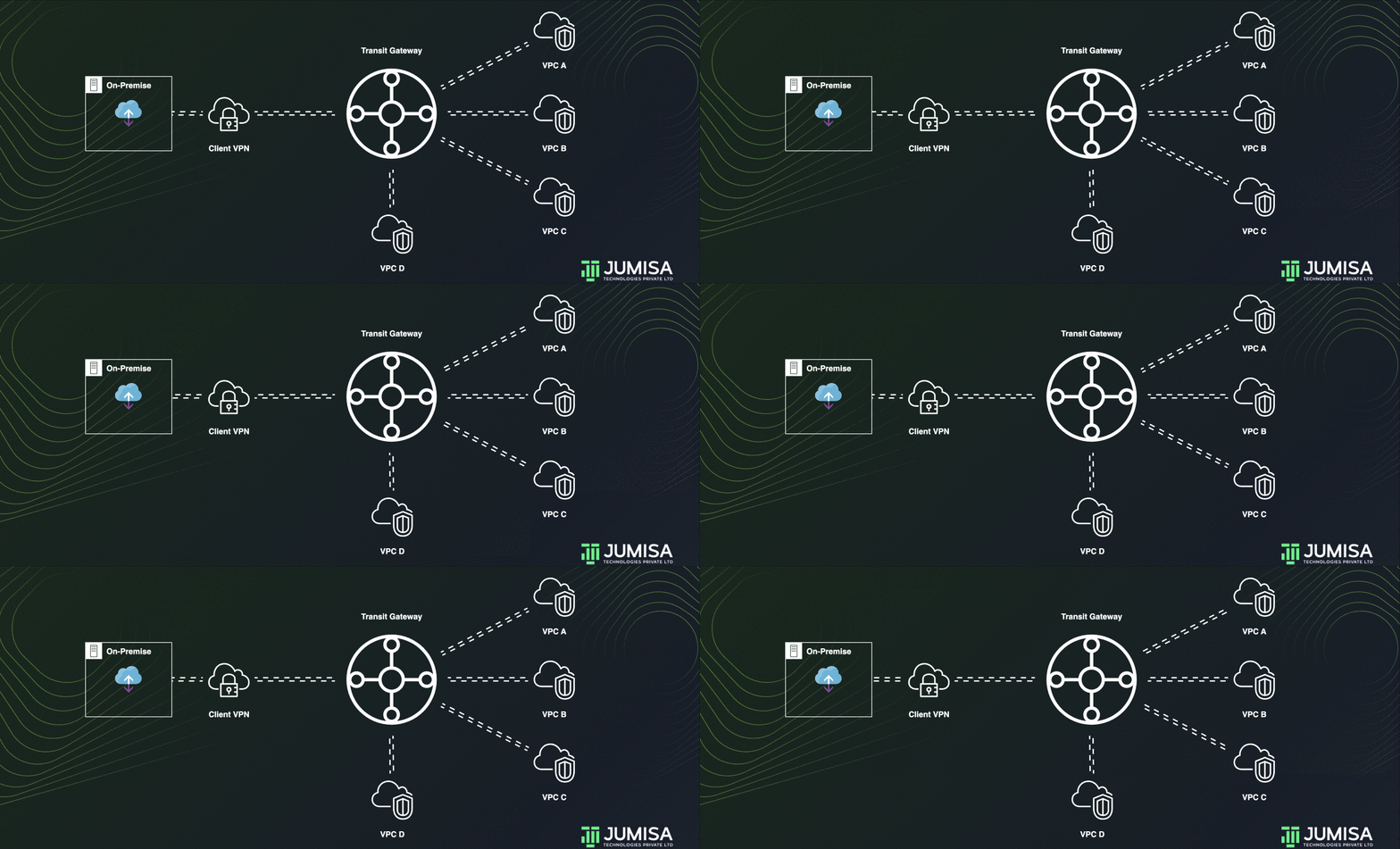
This is like a transit gateway for isolated VPCs. Additionally, attachments can route packets to or receive packets from the shared services.
This scenario is useful when there are groups that need to be isolated, but use a shared service. For example, a production system.
Let us assume some services in VPC D are to be shared with VPC A, VPC B, and VPC C. But all of them are to be isolated.
To achieve this, the TGW for isolated services can be modified by adding a route entry for the VPC D in the TGW route table for VPN as shown below.
| Destination | Target | Route type |
|---|---|---|
| VPN CIDR | Attachment for VPN connection | propagated |
| VPC D CIDR | Attachment for VPC D | propagated |
Transit Gateway Peering
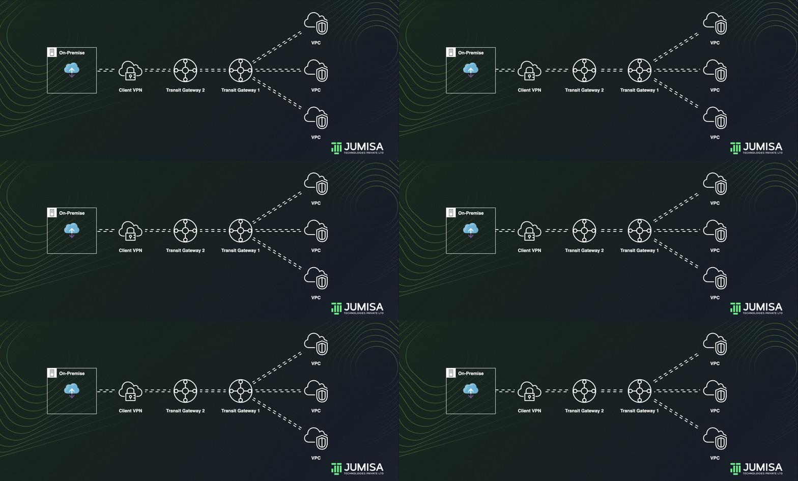
Transit gateways can be peered with each other to allow the resources attached to one TGW to access the resources attached to another TGW.
Peering between transit gateways can be done by adding a static route in the transit gateway route tables.
Let us assume we have TGW 1 which is attached to two VPCs and TGW 2 which is attached to a VPN connection.
On the route table of TGW 1 the VPN from the TGW 2 must be attached as shown below.
| Destination | Target | Route type |
|---|---|---|
| VPC A CIDR | Attachment for VPC A | propagated |
| VPC B CIDR | Attachment for VPC B | propagated |
| VPN CIDR | Attachment for peering connection | static |
And on the route table for TGW 2 the VPCs from the TGW 1 must be attached as shown below.
| Destination | Target | Route type |
|---|---|---|
| VPN CIDR | Attachment for VPN connection | propagated |
| VPC A CIDR | Attachment for VPC A | static |
| VPC B CIDR | Attachment for VPC B | static |
Centralized outbound routing
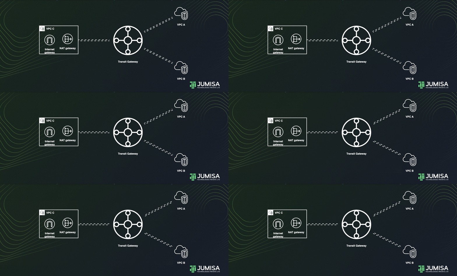
Let us assume the VPC A and VPC B do not have any outbound connections. The VPC C has an Internet gateway and a Nat Gateway attached to it as shown below.
Public subnet route table:
| Destination | Target |
|---|---|
| VPC C CIDR | Local |
| 0.0.0.0/0 | Internet gateway |
Private subnet route table:
| Destination | Target |
|---|---|
| VPC C CIDR | Local |
| 0.0.0.0/0 | NAT gateway |
A Transit gate way can share the NAT and Internet gateway from one VPC to other VPCs thus enabling centralized outbound routing.
This can be done by adding a static route in the transit gateway route table as shown below.
| Destination | Target | Route type |
|---|---|---|
| VPC A CIDR | Attachment for VPC A | propagated |
| VPC B CIDR | Attachment for VPC B | propagated |
| VPC C CIDR | Attachment for VPC C | propagated |
| 0.0.0.0/0 | Attachment for VPC C | static |
Appliance VPC
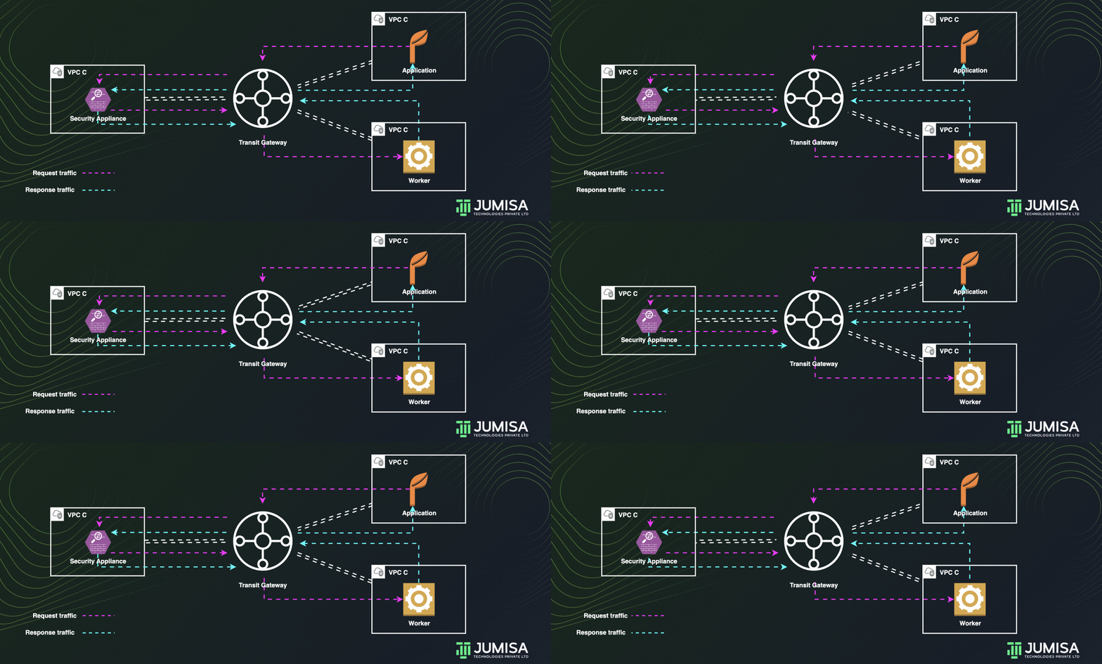
A transit gateway can be used to route all traffic across multiple VPCs through an appliance in a shared VPC.
To achieve this, an additional route table is added to the transit gateway other than the usual one which has the attachments for the VPCs.
Let us assume that the traffic VPC A and VPC B must be routed through a security appliance in VPC C
The default route table for the transit gateway will have propagated attachments for VPC A and VPC B as shown below.
| Destination | Target | Route type |
|---|---|---|
| VPC A CIDR | Attachment for VPC A | propagated |
| VPC B CIDR | Attachment for VPC B | propagated |
There will be one more route table with static attachments for the VPC C as shown below.
| Destination | Target | Route type |
|---|---|---|
| VPC A CIDR | Attachment for VPC C | static |
| VPC B CIDR | Attachment for VPC C | static |
| VPC C CIDR | Attachment for VPC C | static |
Create Transit Gateway
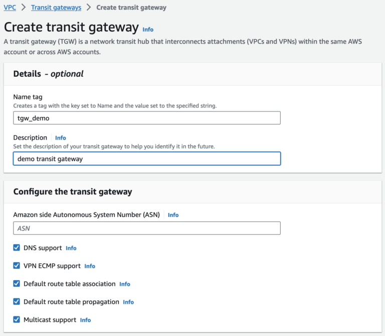
When creating a transit gateway, a default transit gateway route table is created and used as the default association route table and the default propagation route table.
The Autonomous System Number (ASN) for the AWS side of a Border Gateway Protocol (BGP) session. You can use the default ASN, or you can specify a private ASN in the 64512-65534 or 4200000000-4294967294 ranges.
Automatically accept cross-account attachments that are attached to this transit gateway.
A CIDR block of size /24 or larger can be specified (for example, /23 or /22) for IPv4, or a size /64 CIDR block or larger (for example, /63 or /62) for IPv6. Any public or private IP address range can be associated, except for addresses in the 169.254.0.0/16 range, and ranges that overlap with the addresses the VPC attachments and on-premises networks.
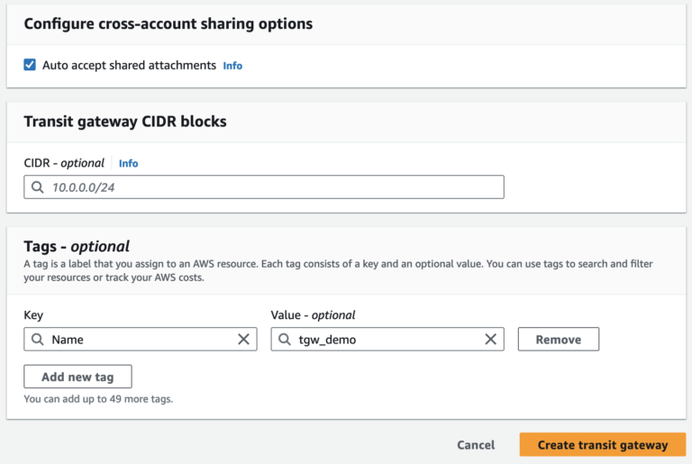
There are two VPCs we have with CIDR range 10.0.64.0/18 and 10.0.0.0/18. Hence, we choose CIDR 10.0.128.0/18 for the Transit Gateway.
Attach VPC to Transit Gateway
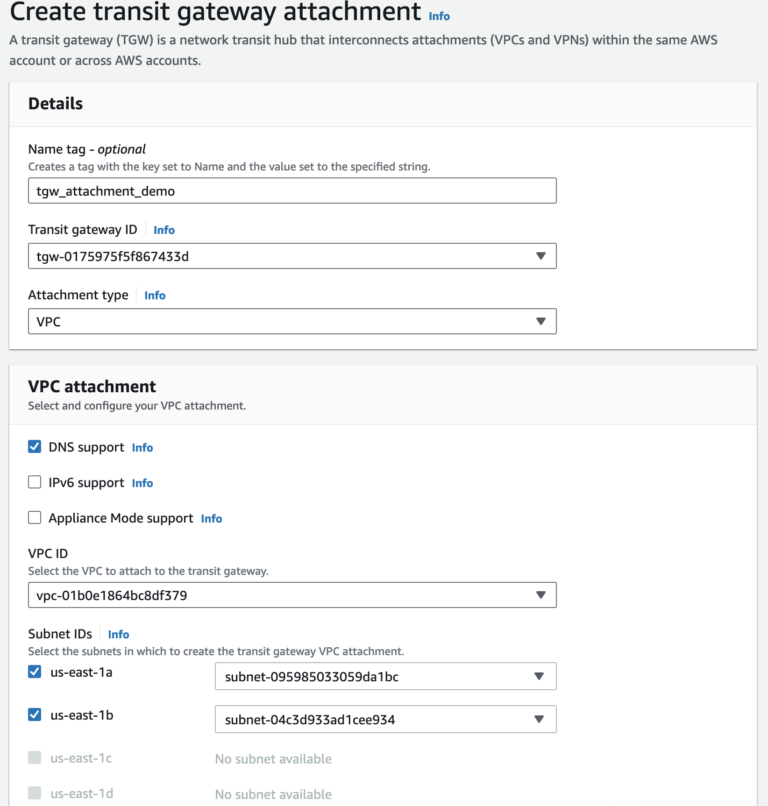
After creating the Transit Gateway, the VPCs are connected to it by Transit Gateway Attachments. For each VPC, an attachment must be created.
Attachment type can be VPC, VPN, connect peer or Peering. The below example is for VPC attachment with DNS support.
Add Routes for TGW and VPC
Each attachment is always associated with exactly one route table. Route tables can be associated with zero to many attachments. To determine the routes to configure, decide on the use case for your transit gateway, and then configure the routes.
A route table includes dynamic and static routes that determine the next hop for associated VPCs based on the destination IP address of the packet. Configure a route that has a destination for non-local routes and the target of the transit gateway attachment ID.

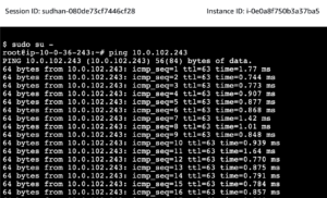
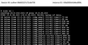
To verify the connectivity, there are two Linux EC2 instances created, one in each VPC.
From the EC2 instance on VPC-1 ping the EC2 instance on VPC-2
From the EC2 instance on VPC-2 ping the EC2 instance on VPC-2
We highly appreciate your patience and time spent reading this article.
Read our article about VPC peering here
Stay tuned for more Content.
Happing reading !!! Let us learn together !!!

